Line Following with Camera
Follow a dark line with an e-puck's camera by finding the line in each image.
Free. Runs in your browser; you'll be asked to sign in first.
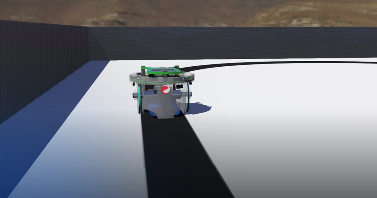
Vision-Based Line Following
Overview
In this lesson, the robot follows a line using a forward-facing camera instead of floor sensors. The camera gives a richer observation, so the control problem starts with perception: detect the line in the image, estimate its lateral position, and steer to keep it near the image center.
The lesson covers a basic perception pipeline and its connection to steering control.
Theoretical Background
Vision-Based Line Detection
A common image-processing pipeline is:
- acquire the image,
- convert it to grayscale,
- reduce noise with smoothing,
- restrict the analysis to a region of interest,
- segment the line or its edges,
- compute the centroid of the detected region.
If \(c_x\) is the line centroid inside the region of interest and \(c_{\text{center}}\) is the horizontal center of the region of interest, the normalized tracking error can be written as:
The centroid comes from the image moments of the region of interest, with each pixel weighted by its darkness \(I(u, v) = 255 - \text{gray}(u, v)\):
Negative \(e\) means the line is left of center. Positive \(e\) means the line is right of center.
Reactive Steering
A simple steering law is:
This is a discrete approximation of a proportional visual-servoing rule.
Task Description
Objective
Implement two functions in line_following_with_camera.py:
detect_line_position(image): convert the camera image to grayscale, smooth it, cut out the region of interest (ROI_TOP,ROI_BOTTOM,ROI_LEFT,ROI_RIGHT), compute the centroid of the dark pixels with image moments and return the normalized offset \(e \in [-1, 1]\) (orNonewhen there is no line).choose_action(line_offset, speed): the action label and the wheel speeds: straight while \(|e| < \varepsilon\) (DEAD_BAND), otherwise turn toward the line, and a safe fallback when the line is not detected.
The main loop reads the image, calls both functions and sets the motors.
System Configuration
- Robot: e-puck differential-drive robot (wheel speeds up to about 6.28 rad/s)
- Sensor: forward camera, 640 x 480 pixels; the lower part of the image shows the floor just ahead;
get_image()returns it in OpenCV's BGR format - Actuators: left and right wheel motors
- Environment: a closed oval of dark line (about 4.7 cm wide) on a bright floor; the robot starts on the line
- Visualization: a Matplotlib window shows the camera image, the region of interest (green) and the detected line position (red dot)
Performance Metrics
A supervisor follows the robot's real position and compares it with the centre of the painted line. The run ends
after one full lap, when the robot is more than 10 cm from the line for 5 s (line_lost), when it stops moving for
5 s (stopped), or after 90 s. It writes:
| Metric | Meaning |
|---|---|
success |
one lap completed, on the line at least 90% of the time |
ended_reason |
lap_completed, line_lost, stopped or time_limit |
time_s |
simulated time of the run [s] |
laps |
laps driven along the line |
distance_m |
path length of the robot [m] |
average_speed_m_s |
distance_m / time_s [m/s] |
mean_line_error_m, max_line_error_m |
distance from the robot's centre to the line's centre [m] |
on_line_ratio |
fraction of the time within 4 cm of the line's centre |
score |
0 to 100: 100 * min(1, laps) * on_line_ratio |
Suggested Algorithm
At each control step:
- Acquire the current image.
- Extract a region of interest near the floor.
- Detect the line and compute its centroid.
- Convert the centroid into a normalized offset.
- Use the sign and magnitude of the offset to choose wheel speeds.
- Apply a safe fallback if the line is temporarily not detected.
Validation Checklist
- The line detector responds correctly when the line moves across the image.
- The offset changes sign in the correct direction.
- The robot turns left for negative offsets and right for positive offsets.
- The robot can continue tracking through moderate curves.
- The controller behaves safely when the line is briefly lost.
References
Extension Ideas
- Replace the discrete policy with a proportional controller.
- Adjust forward speed according to the offset magnitude.
- Improve the recovery behavior when the line is lost.