Navigation Controller (Odometry + PID)
Drive an e-puck to a goal position using wheel odometry and a PID controller.
Free. Runs in your browser; you'll be asked to sign in first.
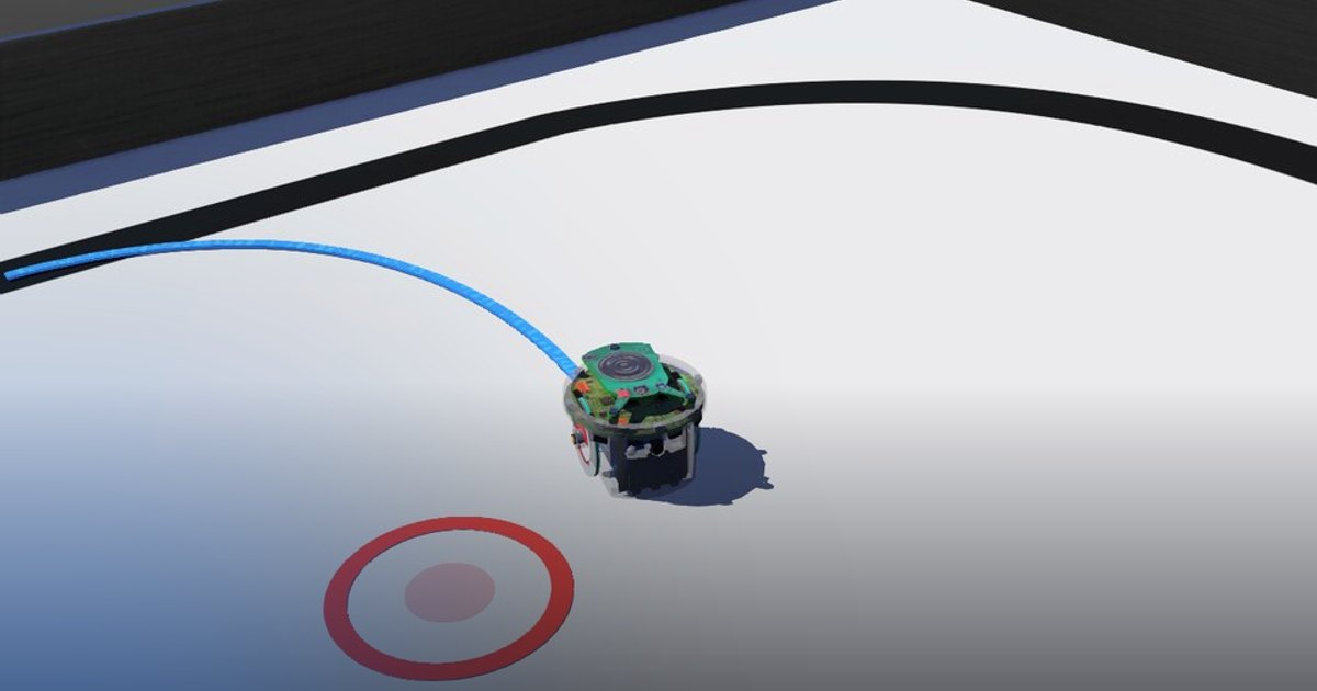
Goal Navigation with Odometry and PID
Overview
In this lesson, the robot estimates its pose from wheel encoders and then uses feedback control to drive toward a target position. The controller measures how far the robot is from the goal, computes motion references from that error, and converts those references into wheel commands.
The lesson covers closed-loop navigation with odometry and PID control.
Theoretical Background
Odometry
Wheel encoder readings are converted into wheel speeds and then into robot linear and angular motion:
The pose is updated every control step, so the controller always uses the latest odometry estimate.
Navigation Error
If the goal position is \((x_d, y_d)\) and the current robot pose is \((x, y, \phi)\), a common choice is:
where \(\phi_d\) is the desired heading from the robot to the goal.
The desired heading is computed with \(atan2\), and the orientation error is wrapped to the interval \((-\pi, \pi]\) so the robot turns through the shorter angle.
PID Control
A simple PID controller has the form:
In this lesson, one controller can regulate forward motion and another can regulate turning.
Task Description
Objective
The odometry functions (get_wheels_speed, get_robot_speeds, get_robot_pose) are provided, from the
localization lesson. Implement in navigation_controller.py:
get_pose_error(xd, yd, x, y, phi): the distance to the goal and the heading error, wrapped to \((-\pi, \pi]\).pid_controller(e, e_prev, e_acc, delta_t, kp, kd, ki): one PID update; returns the output and the updated memory (e_prev,e_acc).wheel_speed_commands(u_ref, w_ref, d, r, max_speed): the wheel speeds for the desired robot speeds, scaled down together when one exceedsmax_speedso that the ratio between them (the path's curvature) is kept.
The main loop runs the odometry, computes the errors, runs one PID for the linear speed and one for the angular speed, sets the wheel speeds, and stops when the distance error is below 1 cm.
System Configuration
- Robot: e-puck differential-drive robot (wheel speeds up to about 6.28 rad/s)
- Sensors: wheel encoders (
get_wheel_encoder_positions(), rad) - Actuators: left and right wheel motors
- Parameters (in the code): wheel radius \(R = 0.02\) m, wheel separation \(D = 0.052\) m
- Initial pose:
get_current_pose()gives the true starting pose once, to initialise the odometry; the robot starts at about \((-0.06, 0.44)\) m - Goal: the origin, \((x_d, y_d) = (0, 0)\), shown in the world as a red target: the filled disc is the 2 cm tolerance
the supervisor accepts, the ring around it stays visible once the robot stands on it. A goal heading (the
supervisor's
goal_yaw) would add an arrow; this lesson grades the position only.
Performance Metrics
A supervisor reconstructs the odometry from the robot's wheel encoders. The run ends when that odometry is within 2 cm of the goal with the wheels stopped for 2 s, when the robot stops away from the goal for 3 s, when the wheels get no commands for 3 s, or after 60 s. That odometry is computed from the real wheel rotations, so it is the best any odometry can do; the robot's real position is reported as well. The difference is odometry drift: the e-puck's wheels slip in fast turns, and the solution typically stops 10 to 15 cm from the real goal while its odometry says 1 cm.
| Metric | Meaning |
|---|---|
success |
the robot settled at the goal according to the wheel-encoder odometry |
ended_reason |
goal_reached, stopped_away_from_goal, no_wheel_commands (the controller stopped before driving) or timeout |
time_s |
simulated time of the run [s] |
time_to_goal_s |
when the robot settled at the goal [s] |
final_distance_m |
real distance from the robot to the goal at the end [m] |
final_distance_odometry_m |
the same distance according to the wheel-encoder odometry [m]; the difference is the drift |
path_length_m |
length of the driven path [m] |
efficiency |
how direct the path was, 0 to 1 |
smoothness |
how smooth the wheel commands were, 0 to 1 |
score |
10 to 100, from reaching the goal (45%), the time to goal (25%), efficiency (15%) and smoothness (15%) |
Suggested Control Pipeline
At each control step:
- Read the wheel encoders.
- Update the odometry pose estimate.
- Compute distance and orientation errors.
- Run the position PID controller and the orientation PID controller.
- Convert the desired robot motion into wheel speeds.
- Saturate the wheel commands if necessary.
- Stop when the distance error is below the goal threshold.
Validation Checklist
- The robot turns toward the goal before or while moving forward.
- The distance error decreases on a successful run.
- The orientation error remains wrapped to a sensible range.
- Wheel commands remain within the motor limits.
- The robot stops once it reaches the goal threshold.
References
Extension Ideas
- Tune the gains for faster convergence with less overshoot.
- Replace the single goal with a sequence of waypoints.
- Add a goal heading: set
goal_yawin the supervisor (the target then shows an arrow) and turn in place at the goal until the orientation error is small. - Add obstacle avoidance before sending the final wheel commands.