Pick & Place
Drive a KUKA youBot to grab a cube from a conveyor with its arm and place it in a cart's empty slot.
Free. Runs in your browser; you'll be asked to sign in first.
Pick and Place with a Mobile Manipulator
Overview
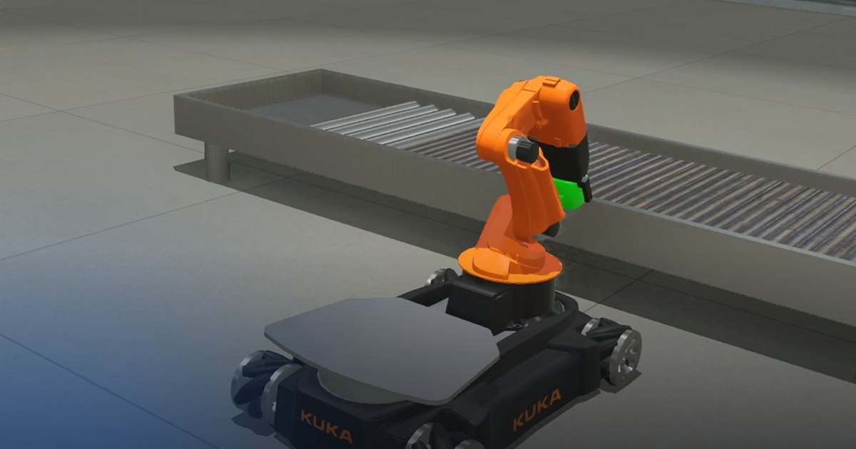
A KUKA youBot stands next to a conveyor belt. The belt brings a green cube to the pick station; the robot must pick it up, drive to a platform cart and put it in the cart's one empty slot, as fast as it can. The slot is only 3 cm wider than the cube, so the cube has to arrive exactly over it, be lowered and let go just above the slot's floor.
The lesson builds the classic manipulation pipeline on a mobile base: base kinematics (mecanum wheels), frame transformations, a pose controller for the base, and the forward and inverse kinematics of the youBot arm. Every arm target is given in the world, turned into the robot's frame with the pose the robot really has, and solved with inverse kinematics; the base only needs to stop roughly in place, the arm makes up the rest.
Theoretical Background
Frames
Three frames are used:
| Frame | Origin | Axes |
|---|---|---|
| World \(W\) | the floor's centre | \(x\) east, \(y\) north, \(z\) up |
| Base \(B\) | the base centre, \(h_B = 0.102\) m above the floor | \(x\) forward, \(y\) left, \(z\) up |
| Arm plane | the arm1 axis, \(0.156\) m ahead of the base centre | \(r\) along the arm, \(z\) up |
The base pose in the world is \((x_B, y_B, \psi)\): the GPS gives the position and the inertial unit the yaw \(\psi\). A world point \(p^W = (x, y, z)\) is expressed in the base frame by undoing the translation and the rotation:
The matrix is \(R(\psi)^T = R(-\psi)\), the inverse of the rotation that takes base axes to world axes.
Mecanum base kinematics
Each youBot wheel carries rollers at 45°, so a wheel pushes the base both along its own direction and sideways. With the wheels at \((\pm l_x, \pm l_y)\) from the centre (\(l_x = 0.228\) m, \(l_y = 0.158\) m) and radius \(r_w = 0.05\) m, the wheel speeds that give a base velocity \((v_x, v_y, \omega)\) (forward, left, counter-clockwise, in the base frame) are
The base is holonomic: it can move sideways and turn at the same time, so it can drive straight at a goal pose.
Base pose controller
To bring the base to a goal pose \((x_g, y_g, \psi_g)\), the position error is expressed in the base frame (where the wheels act) and scaled by a gain; the heading error is wrapped to \([-\pi, \pi)\):
The linear speed is limited to \(v_{max}\) by scaling \((v_x, v_y)\) (the direction is kept), and \(\omega\) to \(\omega_{max}\). Far from the goal the base drives at \(v_{max}\); near it the speed falls in proportion to the error, so it stops without overshoot.
Forward kinematics of the youBot arm
The arm has five revolute joints: arm1 turns the arm about the vertical axis, arm2, arm3 and arm4 are pitch joints that move the gripper in a vertical plane, and arm5 turns the gripper about its own axis (not needed here).
flowchart LR
    B[base centre] -->|0.156 m forward| J1[arm1: yaw q1]
    J1 -->|0.033 m forward, 0.147 m up| J2[arm2: shoulder q2]
    J2 -->|L2 = 0.155 m| J3[arm3: elbow q3]
    J3 -->|L3 = 0.135 m| J4[arm4: wrist q4]
    J4 -->|LT = 0.200 m| G[grasp point between the finger pads]
In the arm's plane, measure each link's angle from the vertical, positive leaning forward. The youBot's pitch joints turn about \(-y\), so a positive joint angle leans the arm backwards, and the link angles are
The grasp point's distance \(r\) from the arm1 axis and its height \(z\) (base frame) are the sums of the links:
with \(s = 0.033\) m and \(z_s = 0.147\) m the shoulder's offset. arm1 then turns the plane: \(x^B = a + r\cos q_1\), \(y^B = r \sin q_1\), with \(a = 0.156\) m. The gripper points straight down when \(\theta_3 = \pi\), that is when \(q_2 + q_3 + q_4 = -\pi\).
Inverse kinematics
Inverse kinematics finds the joint angles for a desired grasp point \(p^B\) and gripper tilt \(\beta\) (the angle between the gripper and the vertical, positive tilting the fingertips forward, so \(\theta_3 = \pi - \beta\)). Five joints and four constraints (three coordinates and the tilt) leave arm5 free; it stays at 0.
- Yaw. arm1 points the plane at the target: \(q_1 = \mathrm{atan2}(y^B,\; x^B - a)\), and in the plane \(r = \sqrt{(x^B - a)^2 + (y^B)^2} - s\), \(h = z^B - z_s\).
- Wrist. Step back from the grasp point along the gripper: \(r_w = r - L_T \sin\beta\), \(\; h_w = h + L_T \cos\beta\).
- Two-link arm. The upper arm and forearm form a triangle with the line from the shoulder to the wrist, of length \(d = \sqrt{r_w^2 + h_w^2}\). The law of cosines gives the elbow's bend \(\varphi = \theta_2 - \theta_1\):
With \(|\cos\varphi| > 1\) the wrist is out of reach. Of the two solutions \(\pm\varphi\), the elbow-up one bends the forearm forward (\(\varphi > 0\)). The upper arm's angle is the direction to the wrist minus the angle the forearm adds:
- Joint angles. \(q_2 = -\theta_1\), \(q_3 = -\varphi\), \(q_4 = -(\theta_3 - \theta_1 - \varphi)\), \(q_5 = 0\).
The wrist can reach an annulus of radii \(|L_2 - L_3| = 0.02\) m and \(L_2 + L_3 = 0.29\) m around the shoulder. At the conveyor the cube is near that edge: the base can't come closer because of the conveyor's rail, so the gripper is tilted by \(\beta = 0.35\) rad, which brings the wrist \(L_T \sin\beta \approx 7\) cm closer to the shoulder. Checking the result with forward kinematics (\(\mathrm{FK}(\mathrm{IK}(p)) = p\)) is the quickest test of both.
Joint-space and straight-line moves
When a joint target is sent to the joint position controllers, every joint moves at a limited speed to its angle. Between two poses the grasp point therefore follows a curve, not a straight line: fine in free space (to the carry pose, to the pose above the slot), not near the cube and the slot's walls. There the grasp point is moved along a straight line: at time \(\tau\) after the move began, the target is
and each step solves the inverse kinematics for \(p(\tau)\). The joints follow a target that moves at \(v = 5\) cm/s, so the gripper goes straight down onto the cube, straight up off the belt and straight down over the slot.
Grasping
The gripper's two fingers slide towards each other; the gap between the pads is \(g = 0.0056 + 2u\) m for a finger travel \(u\). Fully open (\(u = 0.025\) m) they leave 5.6 cm, only 6 mm more than the cube, so the grasp point has to be on the cube's centre line within about 3 mm: this is why the arm targets are computed from the measured base pose, not from where the base was meant to stop. The grasp point is set 5 mm above the cube's centre, so the palm clears the cube's top face.
To grip, each finger is commanded half a millimetre past the cube's face, \(u = (w - 0.0056)/2 - 0.0005\) for a cube of width \(w\). The cube stops both fingers, which then push with the motors' force (up to 100 N) and friction holds it. Why not simply close them fully? Then both fingers push with their full force wherever the cube is, so nothing keeps it centred: when the base turns, the cube slides along the fingers' axis, a couple of centimetres, and misses the slot. With targets just past the faces, a finger the cube moves away from reaches its target and stops pushing, while the other keeps pushing it back: the grip centres itself.
The slot's walls stand 5–6 cm above its floor and the finger pads reach below the grasp point, so the cube is not pressed onto the floor: the arm lowers it until its bottom is 2.5 cm above the floor, still inside the slot, and opens the fingers.
Task Description
Objective
Implement, in controllers/pick_and_place/pick_and_place.py:
arm_forward_kinematics(q): the grasp point for given joint angles.world_to_base(point, base_pose): a world point in the base frame.arm_inverse_kinematics(point, pitch): the joint angles for a grasp point and gripper tilt.base_velocity_to_pose(base_pose, goal_pose): the proportional pose controller for the base.mecanum_wheel_speeds(vx, vy, omega): the four wheel speeds for a base velocity.
main() runs the pick-and-place cycle as a state machine and calls them, in this order; read it to see the sequence.
System Configuration
- Robot: KUKA youBot: a base on four mecanum wheels (radius 0.05 m, up to 14.8 rad/s), a 5-joint arm and a two-finger gripper (each finger 0 to 0.025 m of travel).
- Sensors: a GPS and an inertial unit on the base (pose in the world), position sensors on the five arm joints.
- Actuators: four wheel motors (velocity control), five arm joint motors and two finger motors (position control).
- Environment: the conveyor belt (it brings the cube to \((1.0, -0.003)\) m within 4 s), the platform cart with five cubes and one empty slot centred at \((-2.18, 0.81)\) m.
Performance Metrics
The supervisor watches the cube and writes metrics.json:
| Metric | Meaning |
|---|---|
success |
the cube was lifted off the conveyor and rests, released, in the empty slot (within 3.6 cm of its centre, its centre below 0.156 m) for 1 s |
ended_reason |
placed, dropped (the cube fell to the floor), not_picked (still on the conveyor after 30 s) or timeout (60 s) |
time |
simulated time when the cube came to rest in the slot [s] (the run's length otherwise): the lower, the better |
pick_time |
when the cube was lifted off the conveyor [s] |
placement_error_m |
horizontal distance from the cube to the slot's centre at the end [m] |
cube_height_m |
the cube centre's height at the end [m] |
The run ends as soon as the cube is placed, when it falls to the floor, when it hasn't left the conveyor after 30 s, or after 60 s.
Suggested Control Pipeline
At each control step:
- Sense: read the base pose (GPS, inertial unit) and the arm joints.
- Plan: in the current state, take the world target (above the cube, at the cube, above the slot…), express it in the base frame with the measured pose, and solve the inverse kinematics; or compute the base velocity towards the next goal pose.
- Act: send the joint targets, the wheel speeds or the gripper command.
- Move on to the next state when the arm has reached its joint targets, the base its pose, or the gripper has stopped.
stateDiagram-v2
    [*] --> APPROACH
    APPROACH --> PRE_GRASP: base at the pick pose, cube delivered
    PRE_GRASP --> DESCEND: gripper above the cube
    DESCEND --> GRASP: grasp point on the cube
    GRASP --> LIFT: fingers stopped on the cube
    LIFT --> CARRY: cube off the belt
    CARRY --> TRANSPORT: arm folded
    TRANSPORT --> PRE_PLACE: base at the cart
    PRE_PLACE --> LOWER: cube over the slot
    LOWER --> RELEASE: cube in the slot
    RELEASE --> RETREAT: fingers open
    RETREAT --> DONE
Validation Checklist
world_to_baseof the base's own position is \((0, 0, -h_B)\), and a point 1 m ahead of the base has \(x^B = 1\) whatever the yaw.mecanum_wheel_speeds(0.1, 0, 0)gives four equal speeds of 2 rad/s;(0, 0.1, 0)makes the base slide left.- The base reaches the pick pose without running into the conveyor's rail.
- At the start the console prints the grasp point of the straight-up arm: \((0.189, 0, 0.637)\).
arm_forward_kinematics(arm_inverse_kinematics(p, beta))returnsp; the grasp point printed at the GRASP transition is the cube's centre in the base frame, within a few millimetres.- Every arm target respects the joint limits (arm4 within \(\pm 1.78\) rad): a target the motors can't reach leaves the arm waiting forever.
- The cube stays centred between the fingers while the base turns, goes down inside the slot, and the supervisor
reports
"success": true.
References
- KUKA youBot in Webots
- Mecanum wheel
- Inverse kinematics
- K. M. Lynch and F. C. Park, Modern Robotics, chapters 4 (forward kinematics), 6 (inverse kinematics) and 13 (wheeled mobile robots): modernrobotics.org
- Webots Supervisor API
Extension Ideas
- Make it faster: move the arm while the base drives (fold the arm on the way out, prepare the place pose on the way in), raise the speeds, and see where the cube starts to slip.
- Replace the joint-space approach moves with straight-line moves: interpolate the grasp point between two targets and solve the inverse kinematics at each step.
- Use arm5 to turn the cube so its faces line up with the slot's walls, whatever the base's final heading.